Why Turbulence Defeats Non-Contact Level Sensors
Non-contact level sensors — ultrasonic and free-space radar alike — operate on a straightforward principle: transmit a signal downward, measure the time it takes to reflect off the liquid surface, and calculate distance. That principle holds up beautifully in a calm tank. In an agitated vessel, it breaks down fast.
Ultrasonic sensors are the first to struggle. Breaking waves scatter the acoustic signal in every direction. The sensor receives fragmented, inconsistent echoes rather than a clean reflection, and the resulting level reading bounces erratically with the surface motion. In tanks with high-speed agitators, the signal loss can be severe enough that the transmitter simply drops out entirely and holds its last valid reading — which may be minutes old by the time an operator notices.
Free-space radar handles liquid turbulence somewhat better, but agitated vessels introduce a different problem: physical obstructions. Agitator blades, baffles, dip tubes, and heating coils all return radar signals. The transmitter is receiving reflections from multiple sources simultaneously, and its echo processing algorithm has to pick the right one. In a heavily internalled reactor, this is a genuinely difficult signal processing problem. False echoes get locked onto, or the true liquid surface echo gets lost among the clutter.
The deeper issue is that both technologies are measuring the surface — and in an agitated vessel, the surface is precisely where the process is most chaotic.
The Damping Trap — When the Fix Becomes the Problem
The instinctive response to a noisy level reading is to increase signal damping. Turn up the damping constant, and the transmitter output smooths out. The trend on the DCS looks clean. The operator stops calling the instrument shop. Problem solved — or so it appears.
What damping actually does is time-average the signal. A transmitter with a 30-second damping constant is reporting the average of the last 30 seconds of measurements. In a batch reactor where level changes slowly during a long reaction phase, this is harmless. But in a process where level can change rapidly — a fast fill, an emergency drain, a boilover scenario — a heavily damped transmitter is dangerously slow to respond. It may show a steady, believable level reading while the actual liquid is already gone or overflowing.
This is the damping trap: operators apply enough damping to make the reading look stable, then trust that stable reading in situations where it no longer reflects reality. The fix has become a liability. Recognizing when you’ve fallen into this trap requires looking critically at how fast your process can change and whether your effective measurement response time can actually track it.
The right answer is not more damping on a fundamentally unsuited technology. The right answer is a measurement approach that isn’t defeated by surface turbulence in the first place.
Guided Wave Radar in Agitated Vessels
Guided wave radar (GWR) transmitters solve the turbulence problem by changing where the measurement happens. Instead of transmitting a signal through open air and waiting for a surface reflection, GWR transmitters emit microwave pulses down a probe — a rod, cable, or coaxial element — that extends into the liquid. The signal reflects off the liquid interface at the probe itself, not at the open surface.
Because the measurement point is at the probe rather than the surface, whatever is happening above — waves, foam, vapor, agitator-driven turbulence — has no effect on the measurement. The signal path is defined by the probe geometry, not by the chaotic air-liquid interface. This is why GWR performs reliably in applications that defeat every non-contact technology.
Probe selection matters in agitated vessels. A rigid rod probe works well in clean liquids without significant lateral forces, but agitator-induced flow can exert substantial bending loads on a long rigid element. In tall vessels or high-agitation applications, a cable probe with a bottom anchor distributes mechanical stress along the length of the cable rather than concentrating it at the mounting connection. Coaxial probes — a probe-within-a-probe design — offer the highest signal-to-noise ratio and are well-suited to low-dielectric or foamy liquids, though they require clean conditions to prevent buildup bridging the annular gap.
The practical limitation of GWR is that the probe must extend into the liquid and be compatible with the process chemistry, temperature, and pressure. In highly corrosive processes, selecting the right probe metallurgy is critical. In vessels with extremely viscous or coating materials, buildup on the probe can shift the apparent dielectric constant and introduce measurement error. These are manageable challenges, but they require deliberate attention during specification.
Stilling Wells — Creating Calm Inside the Chaos
When probe insertion is impractical — extremely large vessels, processes where a probe would be a contamination risk, applications requiring frequent cleaning — a stilling well offers a different solution. The concept is simple: install a vertical pipe section inside the vessel, open at the bottom and sealed to the vessel wall, that creates an isolated measurement zone hydraulically connected to the main vessel but physically shielded from its turbulence.
Liquid inside the stilling well is at the same level as the vessel — the bottom opening ensures pressure equalization — but the well walls block surface waves, agitator turbulence, and foam from entering the measurement zone. A non-contact sensor mounted at the top of the well sees a calm, flat liquid surface regardless of what the main vessel looks like. Ultrasonic sensors that would be completely unreliable in the open vessel often perform excellently inside a properly designed stilling well.
Stilling well sizing follows straightforward guidelines. The inner diameter should be large enough to accommodate the sensor’s beam angle without wall interference — typically 100mm to 150mm minimum for ultrasonic, with larger diameters beneficial for free-space radar. The bottom opening should be sized to allow adequate liquid exchange without creating turbulence inside the well itself: too large and vessel agitation enters the well, too small and the level inside lags the vessel during rapid changes. A common rule of thumb is bottom opening area of approximately 1/1,000 of the well cross-sectional area (roughly 0.1%), adjusted upward only where rapid level tracking is required — larger openings allow turbulence to enter the well and defeat its purpose.
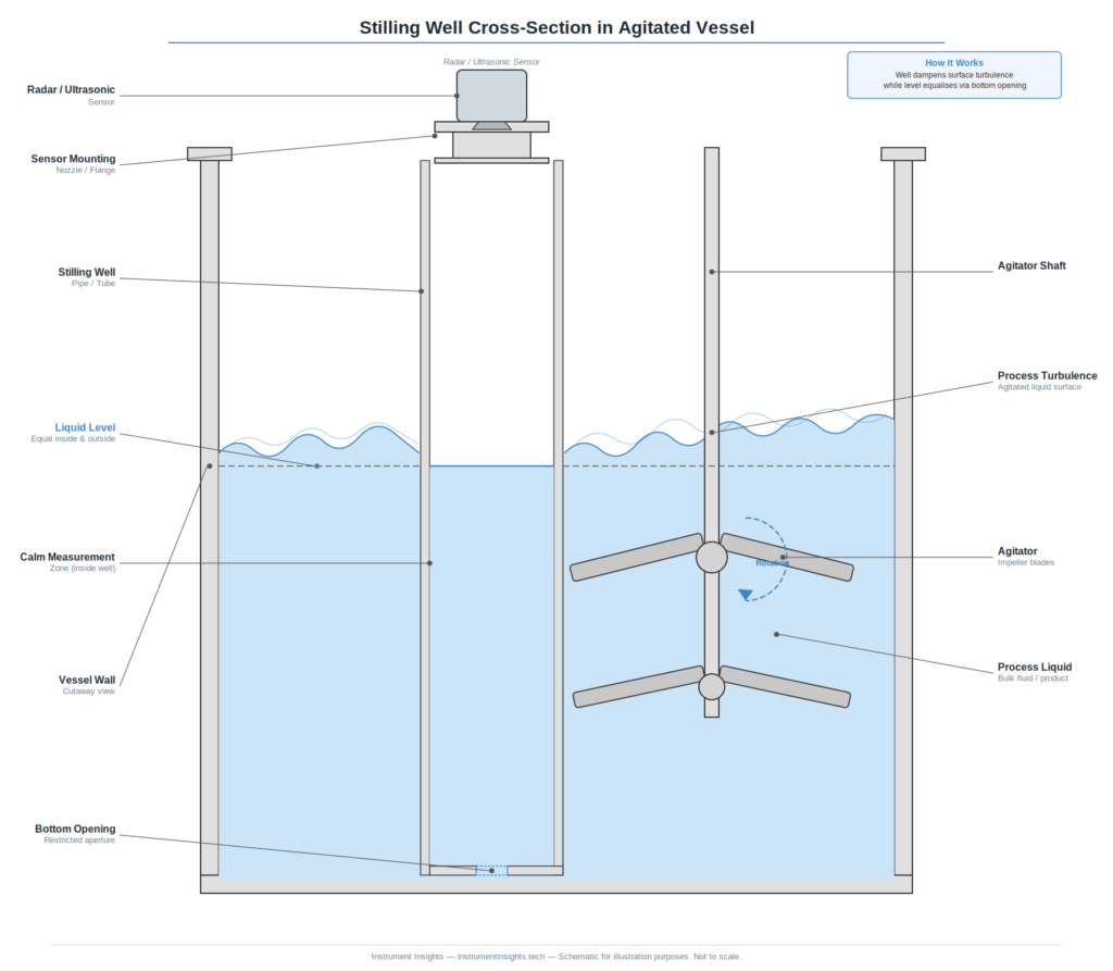
One installation detail that causes problems in the field is stilling well venting. If the well is fully sealed at the top with no vent, gas can become trapped as level rises, creating a false low reading. The well must be vented to the vessel vapor space — either through a small hole near the top or through the sensor housing arrangement — to ensure the gas phase is equalized.
Choosing the Right Approach for Your Application
The choice between guided wave radar and a stilling well is not purely technical — it also involves cleaning requirements, maintenance access, and what existing vessel nozzles you have to work with.
GWR is the faster path in most retrofit situations. You need a single top nozzle of appropriate size, the probe can be removed for cleaning or replacement without vessel entry, and modern GWR transmitters offer diagnostics that tell you when buildup or coating is affecting measurement quality. For most reactors and mixing tanks in chemical, pharmaceutical, and food processing applications, GWR on a top-mounted nozzle is the default first choice.
Stilling wells make more sense when you need to use non-contact technology for hygienic reasons, when the vessel already has a suitable nozzle arrangement for a well, or when process chemistry rules out any metallic probe element. They also work well when a vessel has so many internal obstructions that even GWR would struggle — the well simply bypasses all of it.
In some cases, the answer is neither: differential pressure measurement across a vessel with external impulse lines, or a float-based system in a vessel where those technologies remain viable, may outperform both options in specific applications. The key is to start from an honest assessment of why turbulence is defeating the current measurement and work backward to a technology that addresses that root cause.
The Bottom Line
Surface turbulence is one of the most common reasons level measurements fail in industrial processes — and one of the most commonly mishandled. The instinct to add damping, lower alarm thresholds, or simply accept a noisy reading leads to instrumentation that operators stop trusting. Once trust is gone, the measurement becomes useless regardless of how accurate it technically is.
Guided wave radar and stilling wells are both mature, proven technologies with decades of successful installations in exactly the conditions that defeat ultrasonic and free-space radar. GWR is typically the cleaner solution for most applications: one nozzle, no vessel modifications, straightforward maintenance. Stilling wells require more engineering and fabrication effort but extend the reach of non-contact sensors into applications where probe insertion isn’t feasible.
If you’re dealing with a chronic level measurement problem in an agitated vessel, start by asking honestly whether the technology is fundamentally suited to the application. In most cases, the answer to that question points directly to the right solution.