What a Thermowell Actually Does
A thermowell is a closed-end tube inserted into a process pipe or vessel that allows a temperature sensor to be installed, removed, and replaced without shutting down the process. The sensor — a thermocouple or RTD — sits inside the well and measures temperature through conductive contact with the well tip. The thermowell handles all the mechanical loads: process pressure, flow velocity, vibration, and chemical attack. The sensor inside experiences none of those forces directly.
This arrangement is nearly universal in industrial temperature measurement because it provides two critical operational benefits. First, sensors can be replaced without a process shutdown or pressure break. Second, the thermowell provides a standardized mechanical interface that can be specified independently of sensor type, allowing sensor changes without repiping or requalification of the process connection.
The consequence of this design is that the thermowell becomes a structural element in the process stream. It must withstand static pressure loads, thermal cycling, and — the failure mode that catches many engineers off guard — dynamic loads imposed by flowing fluid. Understanding those dynamic loads is what separates a reliable temperature installation from a maintenance problem waiting to happen.
Vortex Shedding and Resonance — The Failure Mechanism
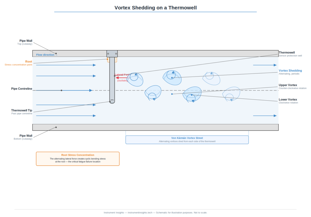
When fluid flows past any bluff body — a cylinder, a flat plate, a thermowell — it separates at the edges and forms alternating vortices downstream. These vortices shed from alternating sides of the body at a frequency that increases with flow velocity. This phenomenon is called vortex shedding, and it is the same principle that makes flags flap in a breeze and causes suspension bridges to oscillate in wind.
For a thermowell, each vortex that sheds imparts a small lateral force on the well in the direction perpendicular to flow. At low velocities, these forces are small and the thermowell deflects imperceptibly. As velocity increases, the shedding frequency increases. When the shedding frequency approaches the thermowell’s natural mechanical frequency — the frequency at which the well would vibrate if struck like a tuning fork — resonance occurs. The well begins to oscillate laterally with amplitudes far larger than the driving force would predict. This is the same mechanism that can bring down a bridge.
In a thermowell, resonance-driven oscillation concentrates stress at the root — the point where the well attaches to the pipe wall or process connection. Material fatigue accumulates rapidly under cyclic stress, and failure can occur within hours of commissioning at high-velocity conditions. The fracture is typically clean and complete, with the well tip and sensor dropping into the process. In high-pressure applications, this is not just an instrumentation failure — it is a potential safety event.
ASME PTC 19.3 TW — The Calculation That Matters
ASME PTC 19.3 TW is the industry standard for thermowell mechanical design and wake frequency calculation. Published by the American Society of Mechanical Engineers, it provides the methodology to calculate whether a given thermowell geometry will remain structurally safe at the expected process conditions — specifically, whether the vortex shedding frequency will stay safely below the thermowell’s natural frequency across the full operating range.
The calculation requires several inputs: thermowell geometry (shank diameter, tip diameter, insertion length, wall thickness), material properties (modulus of elasticity, density), process conditions (fluid density or specific gravity, viscosity, and maximum flow velocity), and the process connection configuration. From these, the standard calculates the Strouhal frequency — the vortex shedding frequency at maximum flow — and compares it to the thermowell’s natural frequency with a required safety margin. A thermowell passes the calculation when its natural frequency is sufficiently higher than the maximum expected shedding frequency. When it does not pass, the design must change: shorter insertion length, larger diameter, heavier wall, or a different profile geometry.
The calculation is not complicated, but it does require knowing your process conditions accurately. The most dangerous mistake is assuming a conservative low value for flow velocity. Thermowells are often installed during initial plant construction and remain in service for decades. Debottlenecking projects, pump upgrades, and increased throughput can push velocities well above original design values. A thermowell that passed its original wake frequency calculation may be operating outside its safe range after a flow increase of 20%. Recalculation is warranted any time process conditions change significantly.
Several thermowell manufacturers offer profiled or tapered designs — stepped or swaged shanks — specifically to improve the wake frequency margin without requiring shorter insertion. These designs shift the natural frequency higher by reducing the tip mass while maintaining adequate stem stiffness. They are worth specifying in high-velocity applications where insertion length requirements would otherwise conflict with structural limits.
Insertion Length — Getting Temperature Measurement Right
Insertion length — the distance the thermowell tip extends into the pipe from the pipe bore — directly determines what temperature the sensor actually measures. This is a point that gets overlooked in the rush to confirm structural adequacy, but it is fundamental to measurement accuracy.
Process fluid temperature at the pipe center is the target measurement. Temperature at the pipe wall is influenced by ambient conditions, pipe insulation quality, and heat losses to the environment — it is rarely the same as the bulk process temperature and can differ by several degrees even in well-insulated lines. A thermowell that terminates in the annular space near the pipe wall is measuring a blend of process and wall temperatures. The sensor output will appear plausible but will be systematically wrong.
The accepted minimum is for the thermowell tip to extend at least 25mm past the pipe centerline. This positions the sensor tip clearly in the core flow where bulk fluid temperature dominates. In steam service or any application where temperature accuracy drives process control, extending the tip to one-third of the pipe diameter past centerline provides additional margin. The goal is to ensure the sensor is immersed in representative bulk fluid, not sitting in the thermal boundary layer near the pipe wall.
Insertion length and wake frequency margin work against each other. Longer insertion improves thermal immersion but reduces structural safety margin. Shorter insertion improves structural safety but may compromise measurement accuracy. Resolving this tension is the core engineering challenge in thermowell specification.
Small-Bore Piping — Special Challenges
Pipes under 3 inches nominal diameter present a specific difficulty: achieving adequate insertion length while maintaining acceptable wake frequency margin becomes geometrically difficult. A standard straight thermowell in a 2-inch pipe often cannot reach centerline at all without creating a structurally marginal installation.
Three approaches address this. The first is an angled thermowell — installed at 30 to 45 degrees to the pipe axis rather than perpendicular. This allows a longer thermowell to reach the pipe center with less actual insertion depth into the flow stream, reducing both the moment arm for vortex-induced bending and the flow obstruction. Angled installations require careful layout to ensure the sensor tip actually reaches centerline given the angular geometry, but they solve the small-bore problem cleanly in most cases.
The second approach is a reduced-bore section — a short spool piece with an expanded bore inserted specifically to provide adequate diameter for a standard thermowell installation. This is a more expensive solution but maintains a perpendicular installation and avoids the layout complexity of an angled well. It is commonly used in critical temperature loops where measurement accuracy is non-negotiable.
The third option, applicable in low-velocity or non-critical applications, is a thermocouple or RTD with an integral connection head installed directly into a fitting without a thermowell. Without the thermowell, wake frequency is not a concern — but the sensor cannot be changed under pressure, and the sensor itself must now withstand all process loads directly. This is an acceptable trade-off in some utility services but is generally not appropriate for critical or high-pressure loops.
The Bottom Line
Thermowell failures from vortex-induced resonance are entirely predictable and entirely preventable. The physics have been understood for decades, the calculation methodology is standardized in ASME PTC 19.3 TW, and the failure mode is well documented. There is no excuse for a thermowell fracture in a well-engineered plant — it is a specification failure, not a random mechanical event.
Before specifying any thermowell in a flowing application, confirm three things. First, run or request a wake frequency calculation using the actual maximum process velocity — not a nominal or design value, but the highest velocity the line could realistically see. Second, verify that the insertion length will place the sensor tip at least 25mm past centerline, and understand what you are measuring if it does not. Third, in small-bore piping, choose an installation geometry — angled well or reduced-bore section — that satisfies both requirements simultaneously.
Temperature measurement is deceptively simple at the instrument level. The sensor generates a millivolt signal, the transmitter converts it to a 4-20mA output, and the DCS displays a number. Whether that number reflects the actual process temperature, and whether it will still be generating that signal in five years, depends entirely on decisions made during specification. Make them deliberately.