How Vortex Flow Meters Work — and Why Upstream Conditions Matter
Vortex flow meters measure flow rate by detecting the frequency at which vortices are shed from a bluff body — a solid obstruction of defined geometry mounted across the pipe bore. When fluid flows past the bluff body, alternating low-pressure vortices form and detach from each side in a phenomenon known as the von Kármán vortex street. The frequency of that shedding is directly and linearly proportional to fluid velocity, and from velocity, volumetric flow rate is calculated using the known pipe cross-sectional area.
The measurement principle is elegantly simple. A piezoelectric sensor or capacitive detector mounted in or near the bluff body detects the alternating pressure pulses as each vortex sheds, counts the frequency, and the transmitter electronics convert that frequency to a flow signal. There are no moving parts, no bearings to wear, and no wetted electronics. Vortex meters handle a wide range of fluids — liquids, gases, and steam — and are well suited to the elevated temperatures and pressures found in steam distribution, process gas measurement, and chemical plant service.
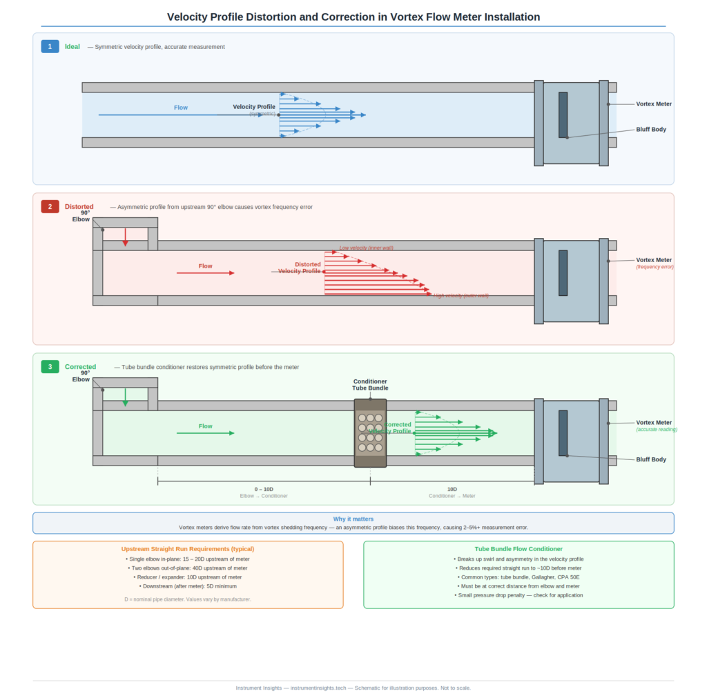
The limitation is this: the vortex shedding frequency is proportional to the average velocity at the bluff body face, and that relationship holds only when the velocity profile across the pipe is symmetric and fully developed. A symmetric, developed turbulent profile — the kind that exists in a long straight pipe far from any fittings — has a predictable shape that the meter’s calibration factor was determined against. When the profile is skewed, swirling, or otherwise distorted, the velocity seen at the bluff body no longer represents the true average pipe velocity, and the meter reads incorrectly. The physics of the measurement makes distorted profiles a direct source of error, not just a theoretical concern.
What Upstream Fittings Do to the Velocity Profile
Every fitting in a piping system introduces some distortion to the velocity profile. The severity depends on the type of fitting, its geometry, and how close it is to the measurement point. Single-plane elbows — a 90-degree bend in a single plane — shift the velocity profile toward the outer radius of the bend. The faster-moving fluid on the outer wall and the slower-moving fluid on the inner wall create an asymmetric profile that can persist for 20 to 30 pipe diameters downstream before naturally relaxing back to a symmetric distribution.
Two elbows in perpendicular planes — a configuration sometimes called an out-of-plane double elbow — are significantly more disruptive. The second elbow introduces swirl on top of the asymmetry from the first, and swirling flow can persist for 50 or more pipe diameters in some configurations. A vortex meter installed downstream of an out-of-plane double elbow with inadequate straight run will experience both asymmetric velocity distribution and rotational flow, both of which produce measurement errors. The errors may be in the same direction, compounding each other, or they may partially cancel — but there is no reliable way to predict the net error without flow calibration under those specific conditions.
Partially open control valves are among the worst upstream disturbances for flow measurement. A butterfly valve or globe valve operating at less than full open creates a jet of high-velocity flow surrounded by turbulent recirculation zones. That disturbance is intense and requires very long recovery distances. Installing a vortex meter downstream of a throttling control valve without adequate straight run is a recipe for unreliable measurement. In most cases, the control valve and flow meter need to be in separated locations in the piping layout, not adjacent to each other. Pumps, especially centrifugal pumps at part load, also introduce swirl from the impeller that travels downstream and affects any flow instrument in the vicinity.
Straight Run Requirements by Fitting Type
Most vortex flow meter manufacturers publish minimum straight run requirements as multiples of the nominal pipe diameter, expressed as upstream D and downstream D. The standard baseline for a single elbow in one plane is typically 15 to 20 pipe diameters upstream and 5 pipe diameters downstream. These numbers represent minimums, not targets — meeting the minimum gets you to within the meter’s stated accuracy specification; more straight run only helps.
For two elbows in the same plane — a U-bend configuration — the same 15 to 20 upstream diameters typically applies, because both bends are in the same plane and the second partially corrects the distortion from the first. Two elbows in perpendicular planes jump the requirement to 25 to 40 diameters upstream depending on the specific meter design and manufacturer recommendations. A partially-open valve within the upstream section drives requirements to 40 or more diameters, and some manufacturers simply recommend against installations directly downstream of throttling valves without a flow conditioner regardless of available straight run.
Reducers and expanders — pipe diameter transitions — distort the profile by accelerating or decelerating the fluid non-uniformly across the cross-section. A concentric reducer upstream requires 15 to 20 diameters; an eccentric reducer, which is used to avoid low points where liquid can collect in gas lines or high points where gas can collect in liquid lines, creates significantly more distortion and may require 25 to 30 diameters. These requirements are not arbitrary — they reflect real calibration data from flow laboratory testing under controlled conditions. Ignoring them doesn’t save money; it shifts the cost to measurement error and the operational problems that come with it.
Flow Conditioners — The Practical Solution for Tight Installations
Field piping rarely cooperates with installation requirements. Equipment layout decisions made during plant design, later modifications that added fittings without accounting for flow measurement impacts, and the physical constraints of existing structures all conspire to leave insufficient straight run. The practical engineering question is not whether the installation is ideal — it rarely is — but how to get acceptable measurement performance from the available piping.
Flow conditioners are devices inserted into the pipe upstream of the flow meter that break up swirl and normalize the velocity profile in a much shorter distance than straight pipe alone could achieve. The most common design is the tube bundle — a cluster of small-bore tubes packed into the pipe bore, typically occupying one pipe diameter of length. The bundle divides the flow into many parallel streams, each too small to carry significant swirl or velocity asymmetry, which recombine downstream into a symmetrized profile. A tube bundle installed 10 pipe diameters upstream of a vortex meter can provide the same profile quality as 20 or more diameters of straight pipe without the conditioner.
Vaned or perforated plate conditioners use a different geometry — a plate with a pattern of holes of varying size — to redistribute flow energy across the pipe cross-section. These designs tend to be more compact than tube bundles, fitting into half a pipe diameter of space, and are effective at correcting both swirl and asymmetric profiles. Some vortex meter manufacturers offer flow conditioner assemblies specifically designed and calibrated with their meter body, with published accuracy specifications for the combined system installed in conditions that would otherwise fall short of the standalone meter requirements.
The installation of a flow conditioner must be validated against the specific disturbance sources present upstream. A tube bundle that corrects single-elbow distortion may not adequately address out-of-plane swirl from a double elbow configuration. When the upstream piping is complex — multiple fittings in various planes, partially-open valves, transitions — the conditioner selection and placement should be based on the specific combination of disturbances present, not generic rules of thumb. This is where a flow calibration facility test, with the actual upstream configuration reproduced, provides the only reliable answer if the application demands tight accuracy.
Downstream Requirements and Backpressure
Downstream straight run requirements for vortex meters are less stringent than upstream requirements but are not zero. The minimum 5 pipe diameters downstream of the meter body keeps backpressure disturbances from propagating upstream into the measurement zone and allows the vortex street to develop and dissipate cleanly behind the bluff body. In liquid service, an additional concern is cavitation — the formation and collapse of vapor bubbles — which can occur if the static pressure downstream of the bluff body drops below the fluid’s vapor pressure.
Backpressure at the meter outlet must be maintained above the cavitation threshold to ensure reliable measurement in liquid service. The minimum backpressure required depends on the fluid’s vapor pressure, the meter’s pressure drop, and the flow velocity. Most vortex meter manufacturers publish a minimum backpressure formula that accounts for these variables. In practice, this means that vortex meters in liquid service should not be installed immediately upstream of pressure letdown valves or at high points in piping where vapor can accumulate. Installing the meter with a downstream control valve that maintains adequate back-pressure — rather than a valve immediately upstream — satisfies both the straight run requirement and the cavitation prevention requirement simultaneously.
The Bottom Line
Vortex flow meters are capable instruments with excellent long-term stability and no moving parts to wear out — but their accuracy depends entirely on the quality of the velocity profile presented at the bluff body. Straight run requirements exist because the physics of vortex shedding measurement demands a symmetric, developed flow profile to produce a valid result. They are not conservative guidelines that can be relaxed when piping space is tight. Ignoring them produces measurement errors that are real, repeatable, and invisible to anyone who doesn’t know to look for them.
When adequate straight run isn’t available — and in most existing plants, it won’t be — a properly selected and positioned flow conditioner provides a legitimate engineering solution. Combined with an understanding of which upstream disturbances are present and how severe they are, a conditioner turns a marginal installation into an accurate one. That’s a much better outcome than redesigning plant piping or, worse, accepting measurement data that no one should trust.