What Impulse Lines Are and Why They Matter
An impulse line — also called a sensing line or instrument line — is the small-bore tubing or pipe run connecting a pressure tap on the process to the pressure transmitter. The transmitter measures the pressure at its own sensing diaphragm, not directly at the process tap. Whatever fluid fills the impulse line between the tap and the transmitter becomes part of the measurement system. If that fluid column changes — because of trapped gas in a liquid service line, trapped condensate in a gas service line, or settled sediment in a slurry application — the transmitter reading changes with it, even if the actual process pressure has not moved.
This is why impulse line installation matters as much as transmitter selection and calibration. A correctly specified, accurately calibrated transmitter connected to a poorly installed impulse line will give unreliable readings. The physics of the fluid column in the line is inseparable from the measurement.
The Slope Rule
The foundational rule for impulse line installation is slope. Any horizontal run of impulse tubing must have sufficient slope to prevent fluid pockets from forming and remaining in the line. The industry standard, codified in ISA-5.1 and widely cited in instrument installation practices, specifies a minimum slope of 1 in 12 (approximately 1 inch of rise or fall per foot of horizontal run, or about 83mm per metre) for impulse lines.
In practice, many experienced instrument technicians prefer to work to a steeper slope wherever routing allows — 1 in 10 or steeper. The steeper the slope, the faster pockets drain and the less likely intermittent pockets are to persist long enough to affect the measurement. The 1-in-12 figure should be treated as a minimum, not a target.
The direction of slope depends on whether the service is gas or liquid:
Liquid service: Slope the impulse line downward from the process tap toward the transmitter. Gas bubbles that form or enter the line will migrate upward, back toward the process tap, and not accumulate at the transmitter. Any high points in the line must be avoided, as gas naturally collects at high points and will not self-purge.
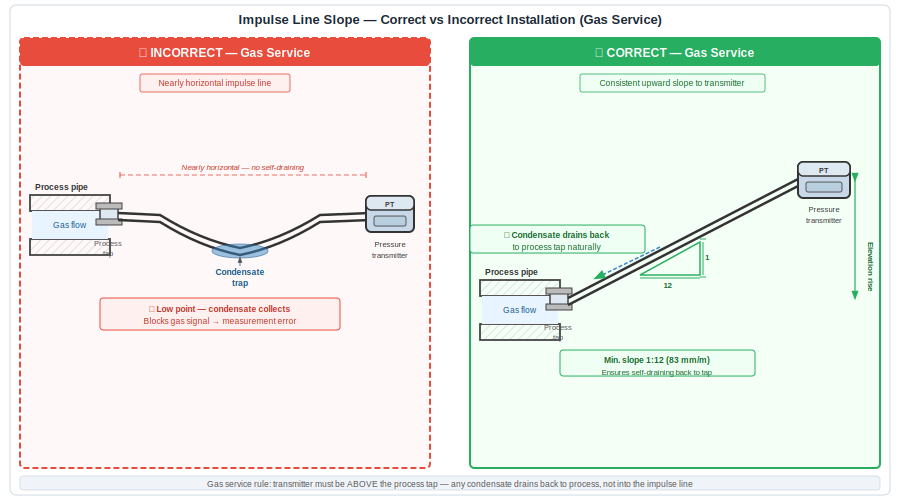
Gas service: Slope the impulse line upward from the process tap toward the transmitter. Condensate that forms in the line as the gas cools will drain back toward the process tap, not accumulate near the transmitter. Any low points in the line must be avoided, as liquid naturally collects at low points and will not self-purge.
Common Installation Mistakes
The most common impulse line installation error is running the tubing nearly horizontally between the process connection and the transmitter because it is mechanically convenient. Instrument runs often share pipe racks with process piping, and it is tempting to follow the rack geometry rather than deliberately slope the instrument line. The result is a slightly undulating run with low points that trap liquid and high points that trap gas — creating measurement errors that can be intermittent, difficult to diagnose, and mistakenly attributed to transmitter faults.
Other common errors include:
Creating unnecessary bends. Every bend in an impulse line is a potential location where the slope changes and a pocket forms. Route impulse lines with as few bends as possible, and verify the slope at each section of the run, not just at the overall run endpoints.
Using undersized tubing. Smaller bore tubing is more susceptible to blockage by sediment or wax deposition. For most industrial applications, 12mm (1/2 inch) OD tubing is the practical minimum. In applications with any risk of sediment, wax, or polymerisation in the connecting fluid, 20mm or larger bore should be considered.
Ignoring thermal effects. In cold climates, exposed impulse lines can freeze, blocking the sensing line and causing the transmitter to read whatever pressure was present at the time of freezing — potentially for hours before anyone notices. Heat tracing and insulation on impulse lines in cold environments is not optional in critical applications.
Steam Applications and Condensate Pots
Steam measurement requires additional consideration because the process fluid at the tap is steam, but the ideal fill fluid in the impulse line is condensate (liquid water). Transmitting steam pressure through a line filled with steam would expose the transmitter diaphragm to high-temperature steam, causing calibration drift from thermal effects on the sensing element and fill fluid.
The standard solution is a condensate pot (also called a siphon pot or seal pot) installed close to the process tap. The condensate pot provides a reservoir of liquid water that forms the top of the condensate column in the impulse line. The transmitter connects to the bottom of this condensate column and measures the pressure transmitted through the liquid — isolated from direct steam contact. A pigtail siphon (a small coil or U-bend in the impulse line before the condensate pot) provides additional thermal isolation and traps the condensate column.
For steam applications, slope the impulse lines — both upstream and downstream of the condensate pot — in accordance with the same liquid-service rule: slope downward toward the transmitter so that any variations in condensate column height drain back toward the condensate pot rather than toward the transmitter. Inconsistencies in the condensate column height translate directly into measurement errors, so maintaining a stable, full condensate column is the primary concern in steam service.
Differential Pressure (DP) Transmitters: Both Legs Matter
Differential pressure transmitters — used for flow measurement across an orifice plate or for level measurement in pressurised vessels — have two impulse lines: a high-pressure (HP) leg and a low-pressure (LP) leg. Both legs must be installed with correct slope and correctly sized to avoid pockets. For liquid-filled DP applications, both legs should be filled with the same fluid to the same level so that the hydrostatic heads on each side are equal and cancel out. Unequal fill heights — caused by one leg developing a gas pocket while the other does not — create a constant zero error that grows or shrinks unpredictably.
For this reason, many DP transmitter installations include equalising valves and drain/vent valves in the instrument manifold to allow the technician to verify fill conditions and purge both legs during commissioning and routine maintenance.
The Bottom Line
Pressure transmitter problems in industrial plants are most commonly impulse line problems — not transmitter failures. Before replacing a transmitter that is giving suspect readings, walk the impulse line from tap to transmitter. Look for low points in gas service, high points in liquid service, and any section of near-horizontal tubing. The 1-in-12 slope rule is the single most important installation parameter for reliable pressure measurement, and it costs nothing to implement correctly during the initial installation.
Get the impulse line right, and the transmitter will take care of itself.