How Magnetic Flow Meters Work — and Why Grounding Matters
Electromagnetic flow meters (mag meters) operate on Faraday’s law of electromagnetic induction: when a conductive fluid flows through a magnetic field, a voltage is induced proportional to the velocity of the fluid. The magnetic field is generated by coils in the meter body, and two electrodes in the pipe wall detect the induced voltage. The signal produced is typically in the range of a few millivolts — small enough to be significantly affected by stray electrical currents and ground potential differences in the plant environment.
This is the fundamental reason grounding is so critical. The electrode signal the transmitter electronics are trying to measure is extremely small. Any stray current that enters or exits the liquid through the pipe connection, the electrode, or the meter body adds directly to or subtracts from that signal. The result can range from a constant offset error (a steady zero shift) to erratic fluctuating readings that make the measurement unusable. In severe cases, the induced voltage from stray currents can entirely overwhelm the flow signal.
Sources of Stray Electrical Interference
Several plant systems are common sources of the stray currents and ground potential differences that affect mag meter performance:
Variable frequency drives (VFDs). VFDs controlling pumps and other motors generate high-frequency electrical noise that can couple into adjacent signal circuits through conducted and radiated pathways. A VFD on a pump in the same pipeline circuit as a mag meter — particularly if the pump and meter share a common ground path — is a very common source of mag meter noise. The rapid switching frequencies of modern VFDs (typically 2–16 kHz carrier frequency) couple efficiently into low-impedance paths like metallic pipework.
Cathodic protection systems. Impressed current cathodic protection systems, used to protect buried pipelines and underground structures from corrosion, deliberately inject DC current into the pipe system. This current travels through metallic pathways — including the pipe connected to a mag meter — and can appear at the electrodes as a significant DC offset. Plants with cathodic protection systems frequently experience mag meter problems in grounded pipework.
Ground loops. Where the pipeline and the meter share multiple ground paths to earth, differences in ground potential between those paths drive current through the common circuit, including through the flowing liquid as the lowest-impedance path. This is particularly problematic where pipework spans between electrically isolated structures with independent ground systems.
Welding operations. Temporary interference during welding near instrumented pipework is common. Welding currents returning through structural steel and pipework create large, brief interference events that can cause mag meters to output transient errors or trigger fault conditions.
Grounding Requirements for Metal Pipe
In a metallic pipe (carbon steel, stainless steel, lined steel), the pipe itself provides a conductive path. The goal is to ensure that the liquid in the pipe is at the same electrical potential as the meter body and the earth ground system, so there is no potential difference driving stray current through the electrodes.
The standard approach is:
Verify that the flanges upstream and downstream of the meter have good electrical continuity through the flange faces and bolts (no PTFE or fibre gaskets that would electrically isolate the flanges). If flanges are isolated by gasket material for other reasons, bonding straps across the flange joint restore electrical continuity.
Install a dedicated earth ground wire from the meter body to a verified low-impedance earth ground point — not to the nearest structural steel, which may be at a different potential than the instrument earthing system. The earth ground conductor should be sized to carry fault current and connected directly to the dedicated instrument earth bar in the substation or control room, or to a driven ground rod with a measured resistance to earth below 5 ohms.
Do not rely on the plant general earth system for the mag meter ground. General earth systems in industrial plants often carry noise from variable frequency drives, welding sets, and other equipment. A dedicated instrument earth that is bonded to the general earth at a single point (to avoid ground loops) is significantly better for sensitive measurement applications.
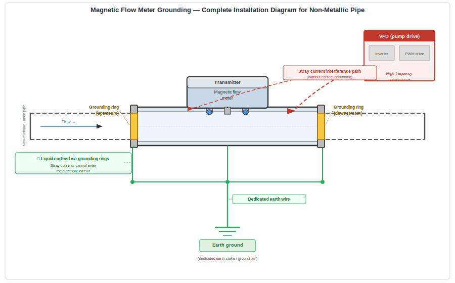
Grounding Requirements for Non-Metallic and Lined Pipe
Plastic pipe (PVC, GRP, HDPE) and rubber or PTFE-lined metal pipe break the electrical continuity between the flowing liquid and the surrounding metalwork. The pipe wall is an insulator. In this configuration, the liquid has no established earth reference — it floats electrically, and stray currents have a free path through the electrode circuit.
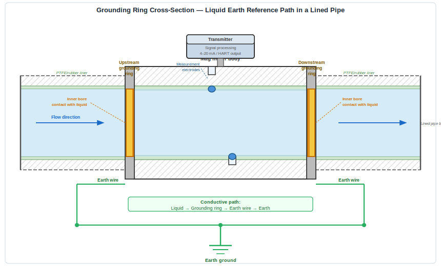
Grounding rings are the solution. A grounding ring is a metallic disc (typically stainless steel or the same material as the flow tube electrodes) that is installed in the pipe flanges immediately upstream and downstream of the meter. The ring contacts the flowing liquid on its inner diameter and is connected by a wire to the meter body and then to earth ground. This establishes an earth reference for the liquid directly adjacent to the measurement section, without adding a conductive path for stray currents to bypass the meter via the pipe wall.
For very aggressive liquids where stainless steel grounding rings would corrode, alternative electrode materials (Hastelloy C, titanium, tantalum) are available. The material should match the electrode material of the meter itself.
In some applications, grounding electrodes integrated into the meter body (as a third electrode positioned specifically for earthing rather than measurement) replace external grounding rings. This depends on the specific meter design and the manufacturer’s recommendation for the pipe material in use.
Verifying Grounding Effectiveness
After installation, grounding effectiveness can be verified with a simple test: measure the potential difference between the liquid (accessible via a conductive fitting downstream of the meter) and the instrument earth with a high-impedance voltmeter. The reading should be close to zero — a few millivolts at most. A larger reading indicates a ground potential difference that will appear at the electrodes as a zero error.
If erratic readings persist despite correct grounding, check for conducted noise on the supply power to the transmitter. VFD-related noise often travels through the power circuit rather than the ground circuit. An isolation transformer on the transmitter power supply can break this path.
The Bottom Line
Magnetic flow meters are inherently sensitive instruments measuring millivolt-level signals. The physics demands a good electrical earth reference and the absence of stray currents at the measurement electrodes. Most field problems with mag meters that are attributed to “sensor failure” or “meter malfunction” resolve when the grounding is correctly implemented.
Before condemning a mag meter that is giving erratic readings — and certainly before replacing it — walk the grounding circuit from the meter body to earth ground. In plastic or lined pipe, verify that grounding rings are installed on both flanges. Measure the ground potential. The answer is usually in the ground.