Why WFI Is Different From Every Other Tank
Water for Injection is among the most tightly controlled process fluids in any industry. Manufactured to USP and pharmacopoeia standards, WFI must be free of pyrogens, particulates, and microbial contamination. Any instrument that contacts the water must meet hygienic design requirements — no crevices, no dead legs, materials that won’t leach into ultra-pure water, and surfaces that can survive aggressive clean-in-place cycles.
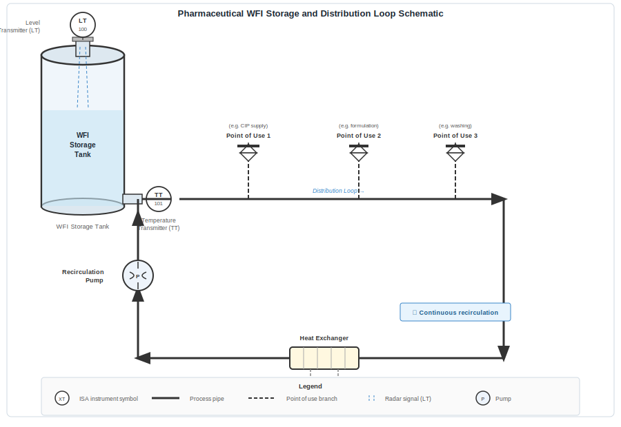
WFI storage tanks run continuously at above 70°C for hot storage — EU GMP Annex 1 specifies above 70°C as the minimum, and many facilities target above 80°C for additional safety margin — or at ≤4°C for cold storage with UV sterilisation. The tank circulates water continuously through the distribution loop — the WFI is never stagnant. Level control must account for this constant recirculation flow, which creates surface turbulence that can fool less capable measurement technologies.
Add the regulatory dimension: every piece of equipment in a WFI system must be validated, calibrated on a documented schedule, and traceable. Level instruments are no exception. The sensor you choose needs to support your validation protocol, not fight it.
Why Contact Sensors Are a Problem
Float switches, capacitance probes, and traditional guided-wave radar all share one problem in WFI applications: they contact the water. Any wetted component is a potential source of contamination and a validation burden. Float switches have pivots and cavities that are difficult to clean. Capacitance probes need surface coatings that must be compatible with ultra-pure water and validated for extractables. Every wetted part must be documented, pressure-tested, and included in the CIP/SIP validation scope.
There’s also the thermal stress issue. WFI tanks operating at elevated temperatures cycle repeatedly as water is drawn off and replenished. Electronic probes with wetted sensing elements experience this thermal cycling directly. Over time, seals degrade, measurement drift occurs, and calibration intervals may need to shorten to maintain accuracy — all of which increases the validation maintenance burden.
The Non-Contact Radar Solution
Non-contact radar level transmitters mount on a nozzle at the top of the WFI tank. The sensor antenna sits in the vapour space above the water — it never contacts the liquid. The only process connection is the nozzle flange or tri-clamp fitting, which can be electropolished to Ra ≤ 0.8 µm to meet hygienic surface finish requirements.
Because there are no wetted sensing components, the instrument is excluded from the CIP/SIP validation scope for the wetted surfaces. The nozzle connection requires validation, but the transmitter itself does not. This significantly simplifies the validation documentation package.
At 80 GHz, modern FMCW radar transmitters have beam widths typically in the 3°–8° range depending on antenna size — significantly narrower than older 26 GHz designs that commonly exceeded 10°. That focused beam is narrow enough to avoid tank internals (spray balls, heating coils, baffles) and to measure accurately in narrow-diameter vertical tanks. The high frequency also provides millimetre-level accuracy on the surface measurement, which matters in tall, narrow WFI columns where the useful measurement range may only be 500–1000mm of actual level variation.
Documentation and FDA 21 CFR Part 11
Modern radar transmitters for pharmaceutical applications support HART and Foundation Fieldbus communication, providing digital access to measurement data, diagnostic information, and calibration records. For facilities subject to FDA 21 CFR Part 11, this data can be logged with timestamps to document storage conditions continuously — not just spot checks.
An important practical note: pair your WFI level transmitter with a temperature sensor on the tank and distribution loop. Storage temperature is itself a critical process parameter for WFI systems, and having both level and temperature on a single instrument loop simplifies the data historian configuration and gives auditors the documentation they need.
Specifying the Right Instrument
When specifying a radar transmitter for a WFI application, key requirements are:
- Hygienic tri-clamp or DIN 11851 process connection in 316L stainless steel
- Electropolished internal surfaces to Ra ≤ 0.8 µm
- PTFE or PEEK antenna material compatible with WFI and clean steam
- FDA-compliant gasket and seal materials (EPDM, PTFE)
- HART or Profibus PA for digital communication and data logging
- 3.1 material certification and surface finish documentation
The investment in a properly specified hygienic radar transmitter pays back in simplified validation, reduced maintenance, and a sensor that genuinely won’t introduce contamination risk into your most critical utility system.